
From:ifixit
We teamed up with The Wirecutter and Ken Shirriff to measure the Swagway’s Swag.
The device that makes walking look pedestrian: the much-blogged-about “hoverboard.” You may have seen those super cool kids, effortlessly gliding around the supermarket while you’re stuck walking the produce section—like a chump. You may have thought to yourself, “Should I get one of those highly advanced, futuristic wheeled-transport platforms? And if I do, will it spontaneously combust, as I’ve seen so many times on YouTube?”
Note: Two-wheel hands-free self-balancing scooter is too hard to say, and this thing definitely does not hover, so we’re going to be calling this a “smartboard.” Deal with it.
Enter The Wirecutter—known for reviews that get to the point (namely, where your dollars ought to go). They took a look at the sea of outwardly identical smartboards and tried to pick a leader out of the pack. After comparing on several factors—such as customer support, warranty, hands(feet)-on testing, and inclusion (or not) of UL-certified components—they selected the Swagway smartboard as their tentative recommendation.
Why a tentative recommendation? Because when these things light on fire, that fire comes from the inside. Merely reviewing the outside isn’t quite sufficient to determine risk. We’re pretty good at taking things apart, so The Wirecutter shipped us a Swagway sample model and we went to town … after running a quick fire drill and testing our fire extinguishers.
Charger
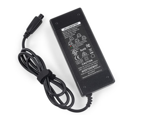
First order of business, the UL-certified charger. There have been reports of smartboards combusting while charging—sometimes at the cost of the owner’s home. A UL listing means a device meets certain safety standards, so hopefully no house fires. This 42 V 2 A charger, manufactured by Shenzhen Fuyuandian Power Co., is indeed registered in UL’sdatabase.
But we can’t stop there. What does a UL-certified charger look like on the inside? Well, if we’re honest, a little messy.
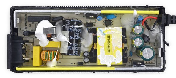
But pretty safe. There’s a lot of ugly looking goop, but beneath that, well insulated and well secured components make us think this thing is unlikely to explode. Looks like a pretty no-frills application of voodoo magic. And by that I mean we’re going to need a little help to decode this device. So we got in touch with charger guru and hobbyist hacker Ken Shirrff of Righto.com, and asked for a bit of help. Here’s what he had to say:
Looks like a straightforward flyback switching power supply. I don’t see any cause for complaints. The separation between primary and secondary looks good—the black line and cutout in the board. There are several ESD discharge points (the “teeth”) to discharge any high voltage. The transformer looks good from the outside. The traces with solder on them are normal: it decreases the resistance and increases the current-carrying capacity: https://www.youtube.com/watch?v=Gy1K3ayPfOk
…The charger looks solid. I don’t see any corners cut. The design is ‘unchallenging’—they didn’t try to make it as small as possible; Apple probably would have made it half the size.

Board
On to the smartboard! We found some super reassuring warning labels (click the image for a better view). Yep, nothing to worry about here.

Looks like someone flunked out of a certification. There’s a suspicious hole in that line of approvals…
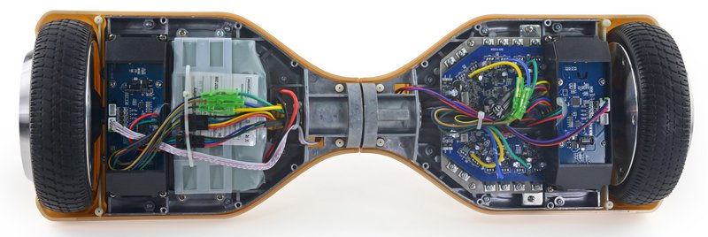
We get our first look inside, and things look… not bad! Given the reputation these boards have garnered, we were expecting to find some serious jank. Instead, at first glance things seem pretty tidy and safe, without any obvious cut corners. Wires and connectors are all safely insulated, the battery and main board are on opposite sides (for balance and to keep them away from each other). Wires passed through the central rotating joint are covered in plastic sleeves to protect them from rubbing.
The Smart Bits
The board is also smart enough to not drive around without you. Riders need both feet firmly planted on the board or it won’t be going anywhere. Just how does the board know you’re properly mounted? Each foot pad has two infrared sensors—one at the toe, one at the heel. Stepping down on the pad pushes a peg between emitter and receiver. Only when all four sensors are blocked are you ready to roll.

Blocking the four infrared emitters assures the board that it has a rider.
Those sensor switches live on the backs of the two gyro boards—one for each wheel. These boards are largely responsible for the “smart” part of smartboard. Each board is home to an Invensense MPU6050 6-axis gyroscope+accelerometer, and a GigaDeviceGD32F130 ARM Cortex-M3 32-bit microcontroller (thanks, Ken!). The ARM chips are responsible for reading the infrared switches, controlling the sweet underglow headlights and top-mounted indicator LEDs, and collating and sending data from the MPU6050 to the main board (more on that later).

One of the two gyro boards, one for each motor.

Image courtesy of Chipworks
For a closer look at the MPU6050 gyro+accelerometer, similar to the 6500 series found in an iPhone 6, Chipworks was happy to share a die photo or two.
Battery
The real star of the show here, and point of most concern, is the firestarter lithium ion battery pack.

Those are some of the handiest tips we’ve ever seen.
Looks like we’ve got a “Shilly-car” lithium battery operating at 36 V with 4.4 Ah (that works out to 158 Wh—just over four times the capacity of an iPad Pro). We’re pretty sure shilly car is a Chinese term for scooter. There isn’t too much to tell from the shrinkwrap. There’s no UL certification on the pack, and no reassuring name brand like Samsung, Sony, or LG—but we can’t judge a battery by its cover.
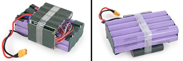
Inside, we find a tidy block of 20 LG batteries with their own protection board. These are LG ICR18650B4 batteries—we’re glad to see a reputable brand in here! These batteries have a nominal voltage of 3.6, and capacity of 2600 mAh. Just for funs, we turned that into Wh (20 batteries * 3.6 V * 2.6 Ah), and got 187.2 Wh. That’s significantly higher than the 158 Wh from the specs on the shrinkwrap. Li-ion batteries should never be fully discharged, so it’s likely that the battery protection board prevents the cells from discharging their full capacity, and the overall battery pack capacity reflects that.
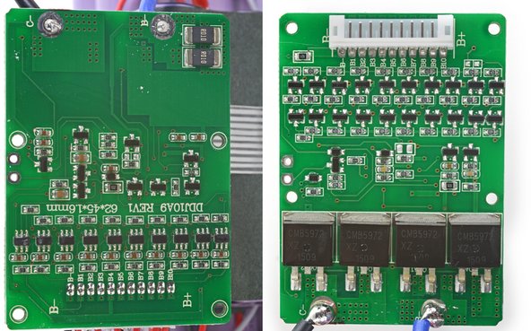
Speaking of the protection board: this is a Shenzen Dalishen Technology DDJ10A9 (the board in that product photo got a much better soldering job than ours). Those four large components are MOSFETs responsible for charging and discharging, and have pretty skimpy solder joints. So far this is the only sketchiness we’ve seen, although it is a bit concerning. These particular solder joints are going to see a lot of power as the battery is charging and discharging.
Motor Control Board
And now we have the motor control board, the heart and brain of the smartboard—it’s responsible for when and where to throw all that battery power. Another GigaDevices ARM Cortex-M3 runs the show here—this time the GD32F103 (the more powerful sibling of the F130 we saw on the gyro boards). Speaking of ARM processors, if you’d like to know more about ARM architecture—our expert witness Ken Shirriff is currently reverse engineering the original ARM1 processor over at his blog righto.com.
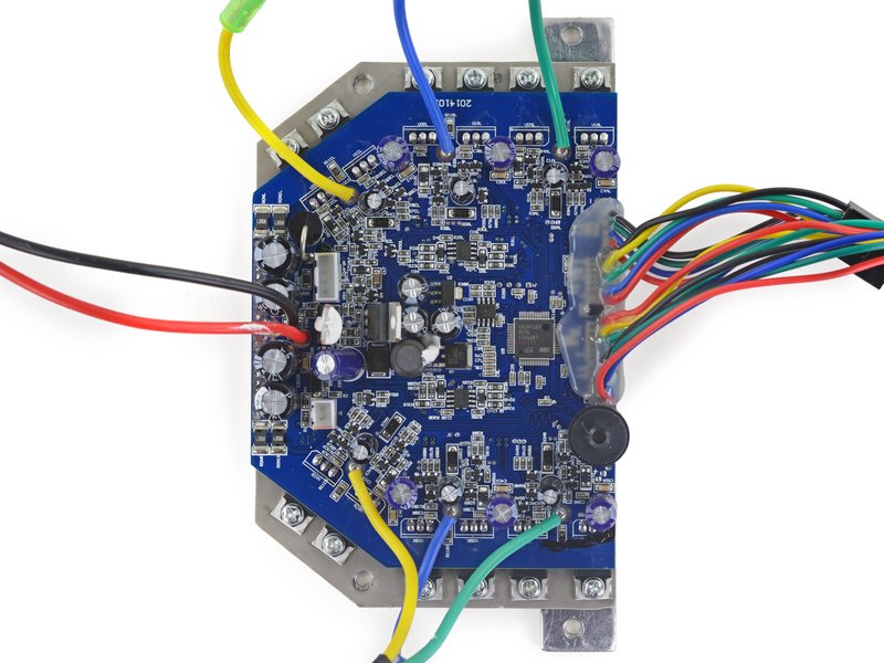
Identified by Ken, the main focus of the control board is the six half-H drivers, which drive two 3-phase motors. If that doesn’t make any sense to you (it didn’t to me), read up on it here: http://ebldc.com/?p=147
The TL;DR is that a brushless motor has no commutator—no mechanical means of switching currents around while the motor spins. So you’ve got to do it with electronics, in a really clever way. Switching currents with electronics means lots of transistors, and switching power to a hefty motor means lots of big transistors. Hence the 12 large MOSFETs surrounding the board, screwed down to a thick metal plate, serving as a heatsink (and, incidentally, as a stiffener and support for the control board).
Also of note are a couple pairs of 0.007 ohm resistors by the power inlet (R007). Resistors like these, with very low resistance, are used to sense current. They’re placed in series with a load, creating a small voltage drop that will be proportional to the current flowing through it (Ohm’s law, V=IR). The microcontroller can read that voltage, apply Ohm’s law, and keep an eye on current. That way it can shut things down if a motor stalls out and tries to burn up (another nice safety feature!). That’s not to say that the smartboard won’t spontaneously combust—it just won’t burn a motor out while you’re rolling around.

Green to blue—what do I do, blue to yellow—kill a fellow?
Taking a closer look at the control board, we find some more minor quality issues. The motor power lines have some interesting (read: completely mismatched) color coordination going on—fixers take note. More worrisome, however, are the uninsulated, unsupported joints attaching these lines to the mainboard. We’d rather see a connector on the board or even a blob of hot glue to support to these big wires. At least they’ve got plenty of solder.
Motors
At this point you might be scratching your head, wondering what actually makes this thing go. Saving the best for last, we cracked open one of the mysteriously heavy wheels to get a look at the previously-hinted-at brushless DC motor. It takes eight wires to run these—three large power leads for the three phases (controlled by the motor control board), and five leads for the Hall effect sensors that track the rotor’s position. The feedback from those sensors lets those big transistors on the motor control board know when to switch, making for a nice smooth ride.
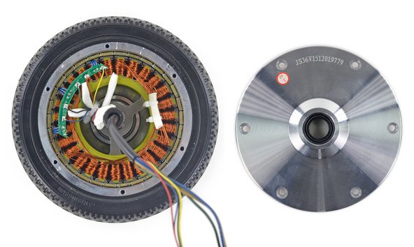
Heavy wheel motor with removed hub cap.
TL;DR
Barring a couple of important nitpicks, this is a well-constructed board.
+ Insulation where it’s needed, good use of connectors and protection against rubbing on wires
+ Current sensing resistors for anti-stall
+ It’s repairable! We tore this thing to the ground and it’s gonna go back together right quick
+ Common Phillips screws, modular components, no desoldering to disassemble
– Poor solder on battery protection board
– Motor leads need some extra support on the control board
All in all, this seems like a good smartboard—but I can’t recommend it as better than the rest without seeing the inside of every other smartboard. At the very least, it probably won’t turn into a Viking funeral pyre on wheels—but no guarantees. Hover at your own risk, friends.
Thanks again to The Wirecutter for providing the board, and to Ken Shirriff for his invaluable electronics excellence.


We also important boards from china. This article was very helpful.
Where does the Bluetooth component lie in the board and how to repair when it does not work?
We also important boards from china. This article was very helpful.
Where does the Bluetooth component lie in the board and how to repair when it does not work?
We also important boards from china. This article was very helpful.
Where does the Bluetooth component lie in the board and how to repair when it does not work?